Keeping you dry - that is one of the most basic functions of a building, along with being structurally sound and not having harmful mold. These all require that a building stay dry.
Most waterproof membranes fail after 10 years so its really important that even without the waterproof membrane that the building is still waterproof. The following details are designed to have redundancy so that when that membrane fails, the waterproofing of the building does not.
Following many failings, both structural and waterproofing of apartment buildings, the NSW Building Commissioner was appointed to raise the quality of apartment buildings in NSW. This has since been extended from Apartment Buildings (Class 2) to Boarding Houses (Class 3) and Aged Care Buildings (Class 9c). The waterproofing philosophy and details below are a summary of the NSW Commissioner's two waterproofing coursed which I highly recommend every architect, builder and developer should enroll in.
Here are the two courses:
Design Principals for Waterproofing - NSW Commissioner
Let it Flow
Design everything so there is a slope so water can flow down
Let it flow is one of the three main design principles when dealing with waterproofing. Let it flow focuses on directing water away from vulnerable areas rather than blocking water contact outright. By redirecting water the risk of capillary action, seepage and waterproof membrane failure is heavily mitigated.
Gravity acts as the main tool when working with this principle. By utilising adequate slopes and drainage systems, gravity will effectively be able to shed water, and prevent it from pooling. Systems that most successfully implement let it flow principles will not hold any water, keeping water flowing from initial contact until the water leaves the building.

Let it Work
Design so that there are a few layers so that even if one fails, the building is still waterproof
The second principle, let it work, focuses on buildability. Good designs often involve finding the simplest solution to complex problems, in order to avoid overcomplicating a situation. Overcomplicated designs can be challenging to build and are more likely to lead to error.
Let it work is about creating designs that forgive the variance that occurs within the construction process. Implementing 'safety nets' in a design can allow a building to more easily mitigate the consequences of error.
Safety nets help to account for the imperfect nature of on site construction conditions and the movement of buildings over time. Multilayered drainage systems are often implement considering let it work principles, acknowledging that if one layer is constructed incorrectly that it will not lead to an overall failure in the overall system.
Let it Move
Design in expansion joints and waterproof them, don't pretend that a building is not subject to movement
Let it move accounts for the fact that buildings change over time. A building's materials can be affected by a range of factors over the course of its life. These factors include temperature, load, moisture and gravity. This can lead to changes in size and shape. When different elements of a building are moving independent of one another it can lead to gaps and cracks, allowing water to seep in.
When considering the let it move principle it is essential to understand that designing buildings as static objects will lead to faults in the waterproofing. Fortunately, movement in buildings can largely be predicted. Good design can foresee exactly how a building moves and utilise that movement to direct water away from high risk areas and towards drainage.
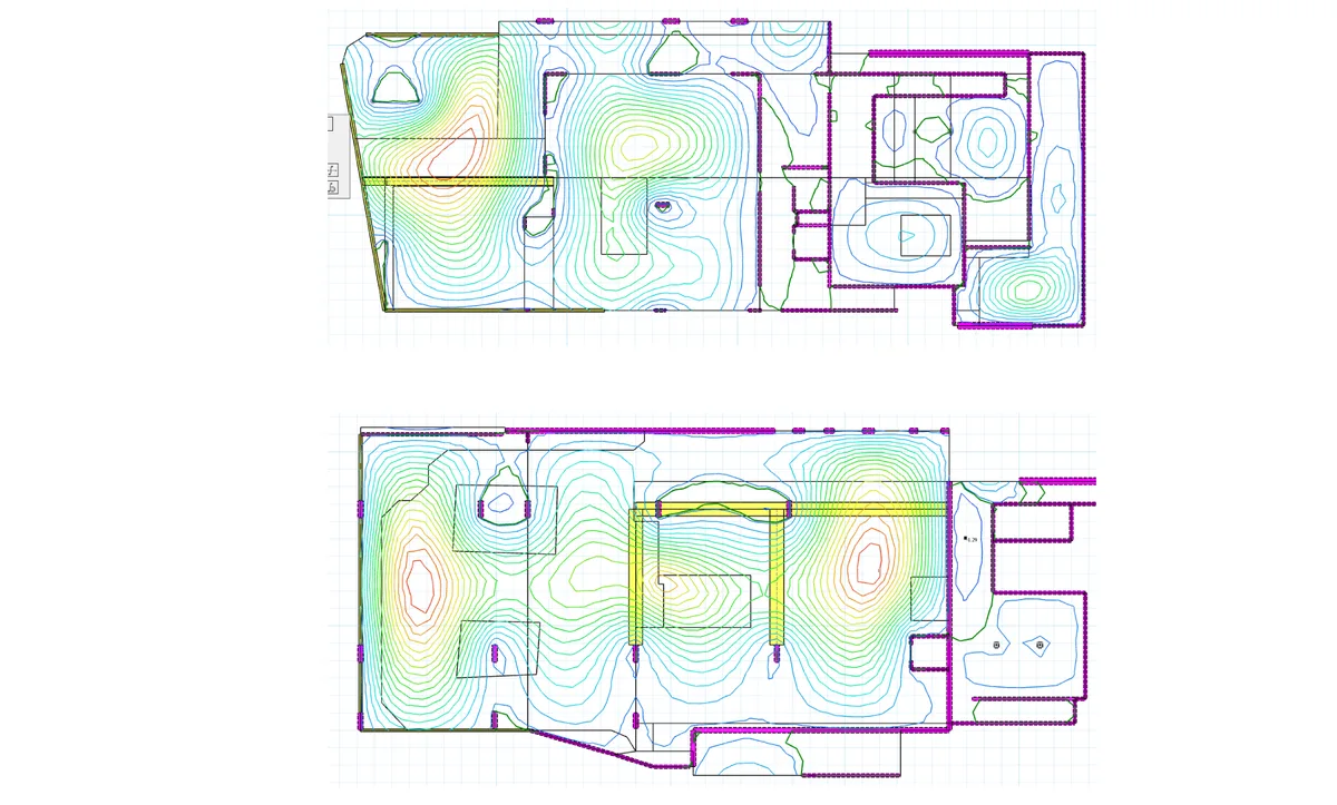
Slab Deflection Plans
Slab deflection plans are structural engineering diagrams that present the change in a slabs shape over the course of time. Slab deflections plans show the regions of a slab most likely to undergo hogging and sagging. Hogging refers to the upward bending or bulging of the slab, while sagging refers to the downward bending. These plans are essential as seeing how the slab will change enables the ability to effectively design to the changes.
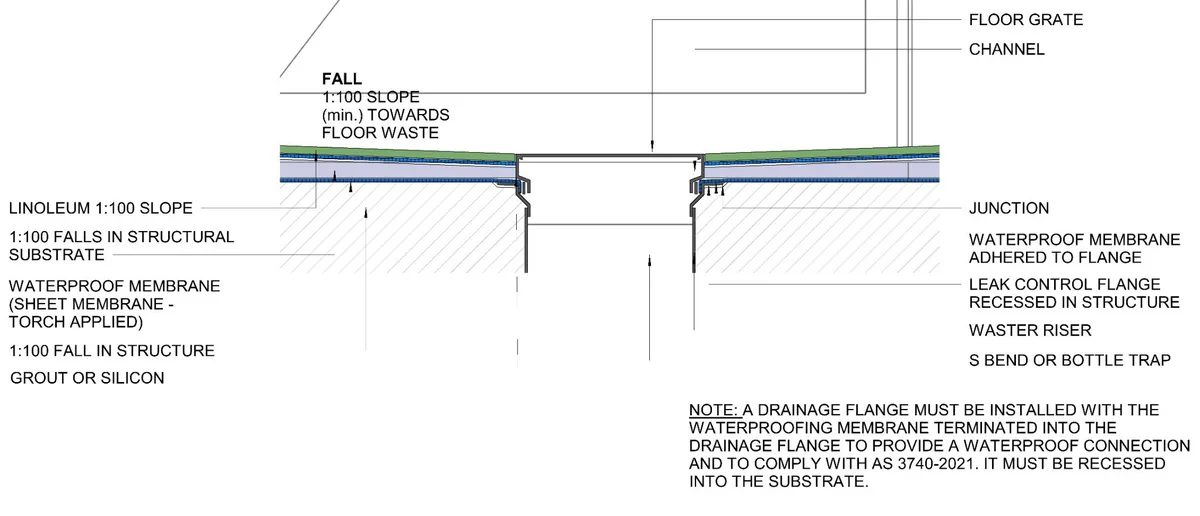
How To Design a Bathroom For Waterproofing
A majority of the problems when working with waterproofing in bathrooms lies in the floors. The main three elements to include when constructing a bathroom floor are a 50mm set down in the structural slab to the whole bathroom area, a 1:80 decline in the showers structural substrate, and a 1:100 decline in the bathrooms structural substrate.
It is important to assess the bathrooms slab deflection plan in order to locate regions of sagging or hogging. Then assess the floor slab thickness and the required substrate sloping of 1:80 and 1:100. In accounting for all of this information it will be easy to calculate an accurate FFL and reduce the room for construction error. This revision of the flooring structure utilises the let it work principle to ensure success.
Sloped flooring provides a way for water to be directed toward the drainage zone through the let it flow principle. Use of slopped flooring provides a number of benefits. Any water that gets through the tiling layer will be able to make its way to the drain and high risk areas like wall junctions will be safe from danger. Additionally, the slab itself is able to provide a continuous barrier to water exit at the room's perimeter.
Waterproofing Detail - Bathroom Floor
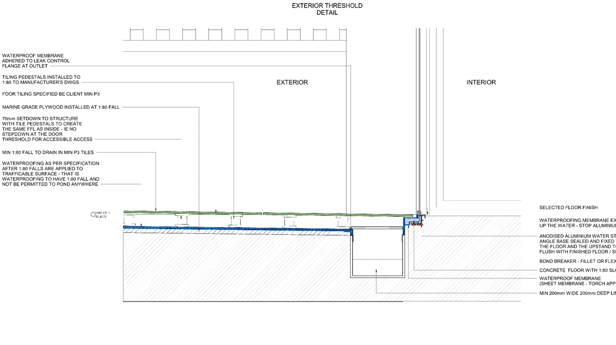
How To Design a Balcony For Waterproofing
When designing areas that are open to the weather is essential to place rainwater elements, namely rainwater outlets and downpipes, in critical locations. When placing these elements consideration must be given to the slab itself. Areas of projected deflection should be located as they will become key water channels over time. Outlets should be placed where sagging is at its lowest.
The ground slab should be constructed with a 1:80 fall to the rainwater outlet. Additionally, a 70mm set down will help in protecting the facade and stopping water from leaking at the wall junction. Calculation of micro-strain and curing procedures must be considered in construction of the slab and shrinkage steel should be included. This will help to reduce the likelihood of cracking and maintain the flow path of water towards the outlet.
In accordance with the let it move principle joints in the concrete slab must be placed away from elements that can get wet. Pour joints and cold joints must not be used in balconies and topping layers and separate pours should be avoided. If used separate slabs with undergo differential movement and lead to leaks.
Waterproofing Detail - Exterior Balcony Threshold
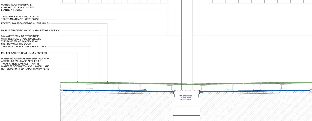
How To Design a Podium For Waterproofing
Often there are large weather exposed slabs that cannot be built as a single slab. As such steps must be taken to minimize the impact of differential movement. With these slabs rainwater outlets must still be placed at the expected low points in the slab, with a 1:80 fall from the slab joint. This will act to draw water away from the joint. A 50mm rise must be cast at the location of the joint for further protection.
A waterproof membrane should cover the slabs, running continuously across the joint. An upward loop of the membrane should be placed centered on the joint as an extra safety net. A slopped sheet metal cap should provide the final layer of protection and should be fixed only to one side of the joint to allow for movement. This detail allows stress to be dispersed across all layers of the structure to create a level of redundancy.
Waterproofing Detail - Podium Floor Drain
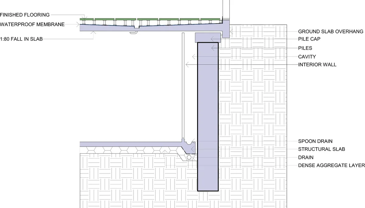
How To Design a Carpark For Waterproofing
Underground car parks pose an extra problem as they must deal with ground water coming in through the floor and walls. Within the wall structure a cavity must be present as it is inevitable that some water will be able to seep through the outer wall layer. The use of a cavity is important to stop the water from jumping to the internal layer by allowing space, free from capillary forces, for gravity to direct the water downward. At the bottom of the cavity should lie a spoon drain to collect the water from the bottom of the cavity.
The floor of the carpark needs to be able to resist the rise of water up from the water table. Drains should be installed at key points such as joints and terminations. Surrounding the drains, a dense layer of aggregate should be employed in order to relieve any hydrostatic pressure and force the water towards the drains. If any additional upward momentum remains upside down drains can be used to discard the remaining water.
Waterproofing Detail - Basement Structure
How To Design Windows For Waterproofing
Windows are one of the most common waterproofing failure points in apartment buildings — every flashing junction, sealant bead and frame profile has to do its job, and the membrane behind has to keep doing its job for decades after the sealant gives up. The two details below show how the head and sill are made to work together: flashings divert visible water, the membrane catches the rest, and a 200mm minimum upturn means a small construction error doesn't become a leak. Hover or tap any number to see what each component does.
Window head detail
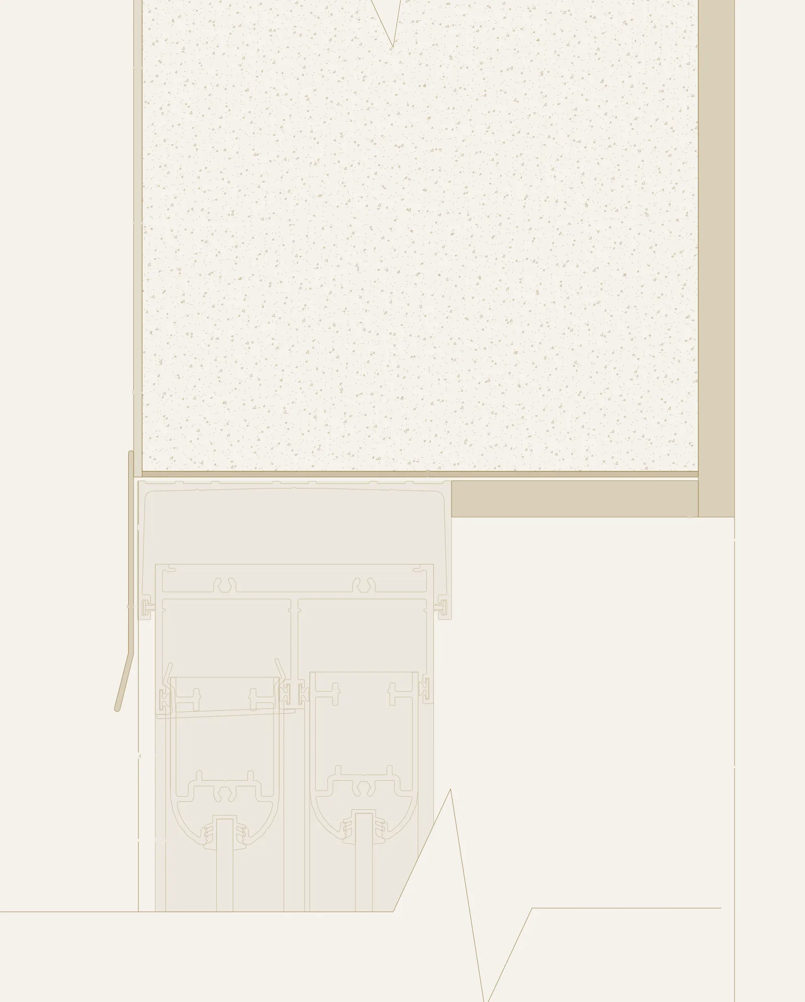
- 1Existing Ritek wall
- 2Make good external render
- 3Waterproofing applied to Ritek after clean and sand
- 4Undertake minor internal reveal gyprock repairs and minor paint works
- 5Installation of new Colorbond drip edge angle surface mounted to existing window frame to deflect facade water shedding and direct away from window
- 6Install flashing to window corners so that it is over sill flashing so water goes to sill flashing and exits
- 7Install flashing to window corners so that it is over sill flashing so water goes to sill flashing and exits, cover with painted aluminum panel to match interior paint
The head detail is about flashing the joint at the top of the window so water sheets clear of the frame. The flashing tucks behind the new render and laps over the head of the existing window — any water that gets past the render finds itself directed back outside.
Window sill detail
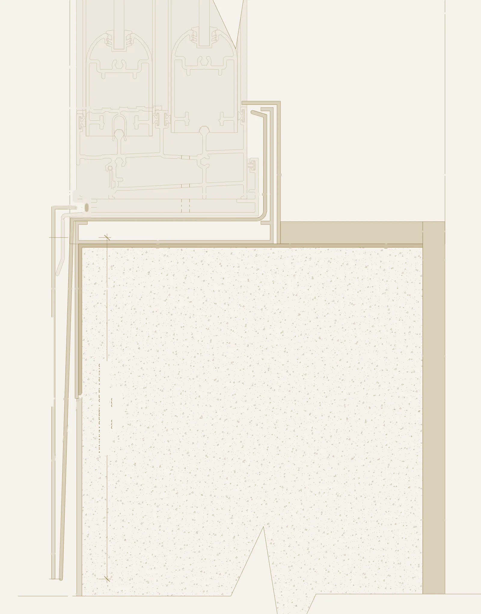
- 1Install flashing to window corners so that it is over sill flashing so water goes to sill flashing and exits, cover with painted aluminum panel to match interior paint
- 2Install flashing to window corners so that it is over sill flashing so water goes to sill flashing and exits
- 3Colorbond cover trim colour matched to existing window frame
- 4Minimum 200mm upturns to flashing according to manufacturer. If that is not possible, have it as high as the internal frame
- 5Gyprock plasterboard
- 6Fatra PVC coated sub-sill tray installed across exposed window sill. Minimum 200mm upturns to flashing according to manufacturer
- 7Waterproofing applied to Ritek after clean and sand
- 8If any rebar is exposed it is to be cleaned, sanded, rust converter/ primer applied and bonding agent applied with high strength non-shrink repair mortar immediately
- 9Aluminum flashing min 200-250mm of flashing on both sides of the window according to Bradnams installation instructions. Colour match to existing window
- 10Undertake minor internal reveal gyprock repairs and minor paint works
- 11Colorbond cover trim which covers the PVC downturn sill tray colour to match existing
- 12Make good external render
The sill is the higher-risk side. Water collecting on the sill has gravity pulling it back into the building. A continuous PVC sub-sill tray with 200mm upturns either side of the opening, plus an aluminium sill flashing dressing the bottom of the frame, gives the assembly two redundant water exits before the membrane behind even gets called on.
How To Design Retaining Walls For Waterproofing
Retaining walls have a constant water source on one side — soil, rain, irrigation, anything that lands on the ground above the wall. The waterproofing has to deal with that water without ever letting it pool behind the membrane, because hydrostatic pressure builds quickly and finds every weakness. The two details below show how a torch-applied membrane, an aggregate drainage layer and a slotted drainage pipe work together: most of the water never touches the membrane, and what does is moving sideways toward the drain rather than pressing inward.
Retaining wall — upper detail
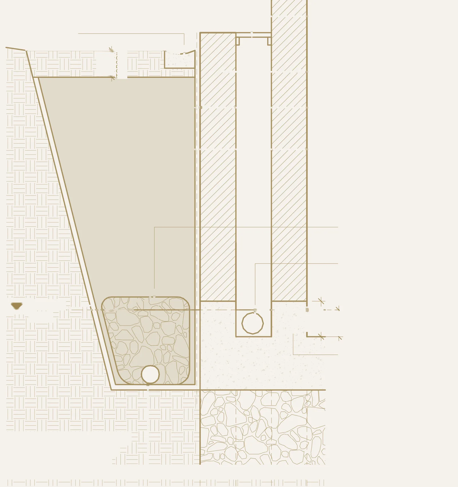
- 1Non combustible drainage grill
- 2Reinforced blockwork wall to structural engineer's DWGS
- 3Torch applied waterproof membrane in accordance with manufacturer's details
- 4Back fill retaining wall with clean fill not clay
- 5Contiguously poured concrete hob
- 6100mm dia slotted pipe in blue metal connected into council stormwater drainage line to be laid to falls and vertical inspection points installed for each
- 7Structural footings to structural eng. DWGS
Detail one shows the upper section: a concrete dish drain catches sheet flow at ground level, the membrane is torch-applied to the back of the blockwork, geo-fabric keeps the soil out of the aggregate layer, and the slotted pipe at the bottom is the relief route for everything that gets through.
Retaining wall — lower detail
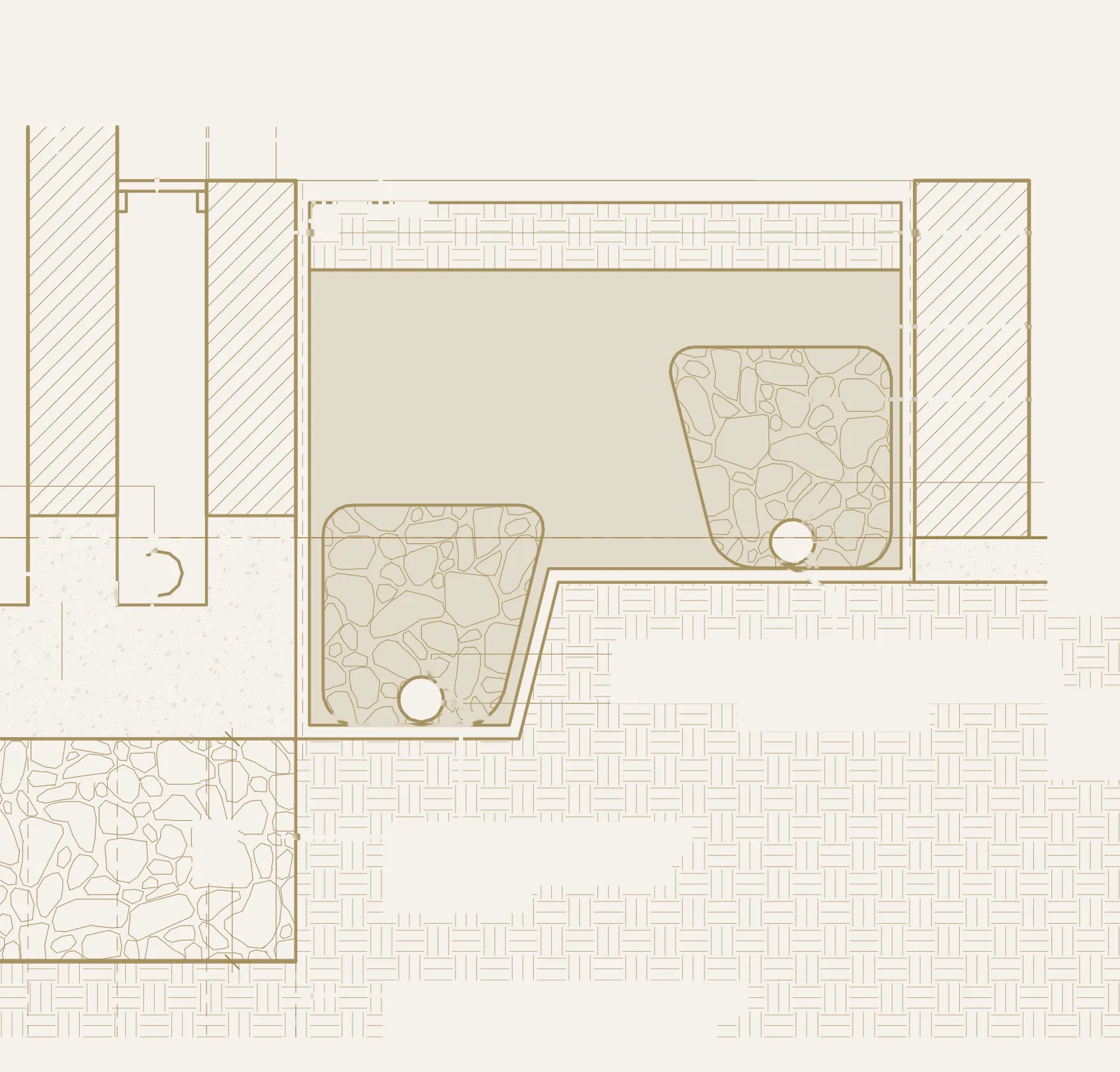
- 1Reinforced blockwork wall to structural engineer's DWGS
- 2Non combustible drainage grill
- 3Torch applied waterproof membrane in accordance with manufacturer's details
- 4Back fill retaining wall with clean fill not clay
- 5Geo fabric silt control throughout
- 6100mm dia slotted pipe in blue metal connected into council stormwater drainage line to be laid to falls and vertical inspection points installed for each
- 7Contiguously poured concrete hob
- 8500mm aggregate to break hydrostatic pressure
- 9Structural footings to structural eng. DWGS
Detail two shows the termination at the base — concrete hob giving the membrane a clean termination, the aggregate layer continuing down to the same slotted pipe, everything connecting cleanly into council stormwater.
